
- Home
- Product
- Types Of Transformer
- Single Phase Transformer
- Three Phase Transformer
- Distribution Transformer
- Power Transformer
- Inverter Transformer
- Solar Transformer
- Electric Arc Furnace Transformer
- Dry Type Transformer
- Amorphous Transformer
- Industrial Transformer
- Heat treatment transformer
- Environment Friendly Transformer
- Low Loss Transformer
- BIS Approved Transformer
- Star Rated Transformer
- Energy Efficient Transformer
- Type Test Transformer
- Ratings Transformer
- Types Of Transformer
- About
- Contact
power and distribution transformer manufacturers in india
Prestige Quality pole mounted distribution transformer, step down distribution transformer suppliers in africa, view power and distribution transformer price
Power And Distribution Transformer Manufacturers In India produce both types of transformers. There are different types and models. the ones produced by Power Distribution Transformer Manufacturers in India are available in the market. Their capacities also differ. There are varieties like 11kv Distribution Transformer, 500 Kva Distribution Transformer, 100 kva distribution transformer, 250 kva distribution transformer and 100 kva pole mounted transformer
distribution transformer manufacturers in india
pole mounted distribution transformer
power and distribution transformer
World-Class 11kv distribution transformer exporter in india, view price of 500 kva distribution transformer, power distribution transformer manufacturers in India
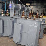
Power transformers
These are used for step up or step down operations in high voltage networks like the transmission ten networks. The differences between the copper loss and the iron loss are managed through optimization of maximum efficiency at full loads. Due to this nature these transformers are designed to operate closer to the knee point at the B-H curve. The core mass can be reduced very much by this strategy. These transformers operate under low fluctuations of load because they are connected on transmission networks. Usually they are loaded throughout the day. The specific weight is very less due to the fact that the copper losses and iron losses take place all the time. Power transformers also operate under very high voltages. They are very efficient above 33KV. Because of the high voltages and transmission network operations, these are highly insulated are usually larger than the distribution transformers in size.
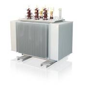
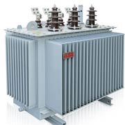
Distribution transformers
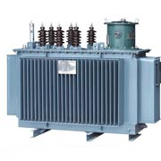
Distribution transformers are used at lower voltages compared to power transformers. They operate at voltage ranges of 220v – 440v in domestic purpose networks. They can operate anywhere below 33KV in industrial networks. Due to the fluctuations in distribution networks, these do not operate at full load at all times. Since their loads differ, their efficiency is also usually low. They are usually rated at ranges less than 200MVA and have less magnetic loss. It sometimes is referred to as the electrical distribution transformer as it is used in electric power distribution systems.
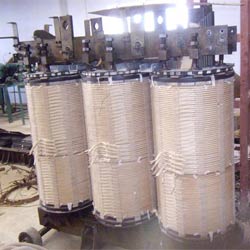
For their operational specifications, distribution transformer winding consists of a magnetic core built with sheet silicon steel laminations. The primary and secondary windings are wound around this magnetic core where the sheets are set together by steel straps or resins. Aluminium wound distribution transformer uses aluminium winding in place of copper. Manufacturers have adopted to this method because of the concern that copper is less available than aluminium. Also, years of testing results have proved that there is not much difference between the two in terms of the quality of operation or performance.
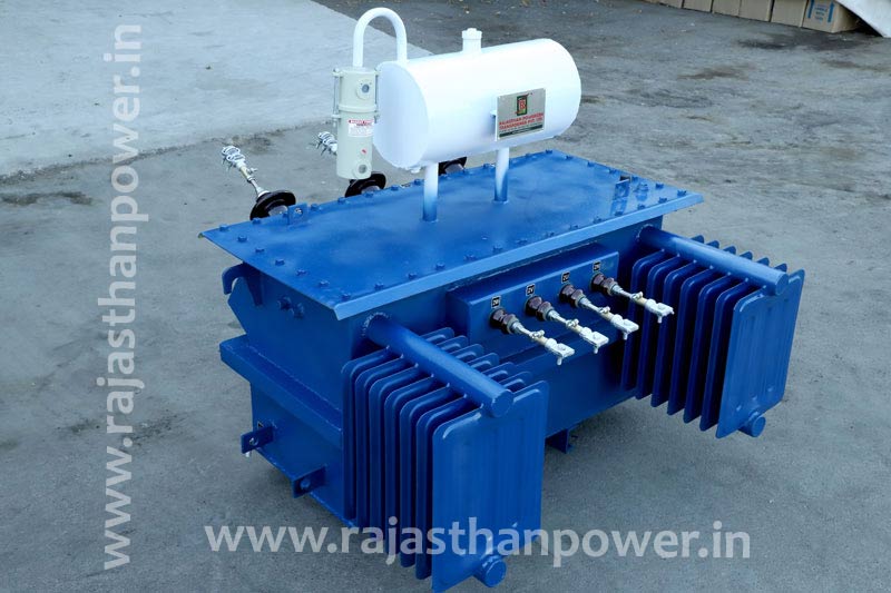
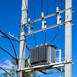
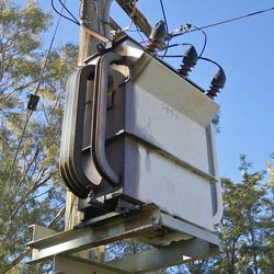
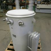
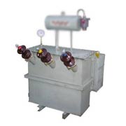
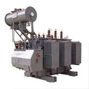
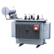
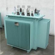
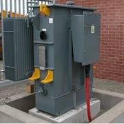
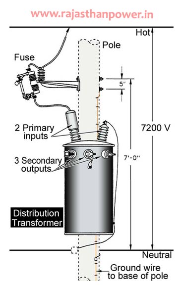
Rajasthan Powergen Transformer P. Ltd. is one of the Distribution transformer manufacturers in India and produce different types of step up and step down distribution transformer units. When mounted on a distribution pole, this is called a Pole Mounted Distribution Transformer.
a distribution transformer definition
Distribution Transformer is an electrical isolation transformer which change over high-voltage power to lower voltage levels worthy for utilize in homes and business.A Distribution Transformer may be a step down transformer essentially utilized for electric control distribution. The step down electric control is at that point utilized for mechanical and person purposes. Ordinary voltage level conveyed from control substations ranges in a few KV extend which are step down by the distribution transformer to approximately 240 volts before it enters and bolstered for residential and commercial utilization. distribution transformer definition
The transformer is usually little in estimate and filled with protection oil. There are different sorts of distribution transformers utilized such as:
- Pad mounted transformer
- Multi phase transformer
- Pole mounted transformer
- Single phase transformer
- Underground transformer
distribution transformer assembly process
This plays a major role in several processes like space utilization, compactness, ease of transportability, handling & installation. Care is taken in every respect for judicious space utilization and that too without compromising with the functional efficiency. Establishing a proper production line in assembly shop always helps in obtaining high production rate.
The wound coils are set carefully within the assembled core. Insulations are given wherever required utilizing materials like press board. The Core bolt and tie bars are settled in position. The Primary and Secondary windings are associated as per the requirement. The complete assembly is kept within the Hot Air Chamber and a high temperature is kept up to anticipate any dampness within the Core coil get together.
emf equation of single phase transformer
| Distribution Ratings | CRGO : Upto 4000 kVA AMT : Upto 2500 kVA |
|---|---|
| Number of Phase | Three Phase |
| distribution Applicable Standards | IS,CEA,IEC,ANSI,JIS,DIN,BS,EN, etc. |
| Cooling | ONAN |
| Insulating Fluid | Mineral Oil as per specification |
| Frequency | 50 Hz, 60 Hz |
| Vector Group | As specified |
| distribution Primary Voltage | Upto 33 kV |
| distribution Secondary Voltage | 415, 433 V (Other Voltages as required) |
| distribution Winding Material | Copper / Aluminium |
| distribution Tapping Range | + 5% in steps of 2.5% (Other tappings as required) |
| Impedance | In line with applicable standards (or) As per customer requirement |
| Distribution Transformer Manufacturers Export to | Kenya, Nepal, Bangladesh, Uganda, Rwanda, Tanzania, India, Nigeria, Malaysia Africa, Malawi |
Distribution Transformer Images
Request A Quote Today For distribution transformer winding, 100 kva distribution transformer, power transformer distribution transformer, 250 kva distribution transformer cost
how a distribution transformer works ?
The most rule of operation of a transformer is common inductance between two circuits which is connected by a common magnetic flux. A fundamental transformer comprises of two coils that are electrically isolated and inductive, but are magnetically connected through a way of hesitance. The working guideline of the transformer can be caught on from the figure underneath.
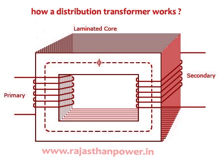
As appeared over the electrical transformer has essential and auxiliary windings. The core laminations are joined within the shape of strips in between the strips you’ll see that there are a few limit crevices right through the cross-section of the center. These staggered joints are said to be ‘imbricated’. Both the coils have high mutual inductance. A common electro-motive force is initiated within the transformer from the alternating flux that’s set up within the covered core, due to the coil that’s associated to a source of rotating voltage.
In brief, a transformer carries the operations appeared below:
- Transfer of electric power from one circuit to another.
- Exchange of electric power without any alter in frequency.
- Transfer with the guideline of electromagnetic induction.
- The two electrical circuits are connected by common acceptance.
distribution transformer construction
According to the design and construction , distribution transformers can be classified into two:
Core- Type Distribution Transformer:
In core-type transformer, the windings are given to a significant portion of the core. The coils utilized for this transformer are form-wound and are of cylindrical type. Such a sort of transformer can be appropriate for little sized and huge sized transformers. Within the little sized sort, the core will be rectangular in shape and the coils utilized are cylindrical. The figure underneath appears the expansive sized type.
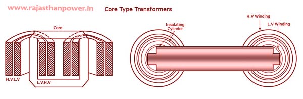
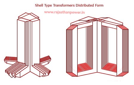
Shell-Type Distribution Transformer:
In shell-type transformers, the core encompasses a impressive portion of the windings. The coils are form-wound but are multi layer disc type ordinarily wound within the shape of pancakes. Paper is utilized to protected the diverse layers of the multi-layer discs. The full winding comprises of discs stacked with cover spaces between the coils. These separator spaces form the horizontal cooling and insulating ducts.
distribution transformer cost
For Final distribution transformer Price India Please Mail Us on info@rajasthanpower.in
distribution transformer uses / distribution transformer application
- distribution transformer use in isolated houses
- farmyards or pumping stations at voltages below 30 kV
- distribution transformer use in power supply of the overhead wire of railways electrified with AC
- distribution transformer used in large commercial or industrial complex
- In urban areas and neighborhoods where the primary distribution lines run underground
- distribution transformer use in power collector networks of wind farms
Distribution Transformer Rating / Indian Standard Rating Of Distribution Transformer
| Description | Max Ratings | Voltages | Standards |
| Amorphous Metal Cores Distribution Transformers | 2.5 MVA | Up to 11kV | ANSI,IEC,IS |
| Cast Resin Dry Type | 1 MVA | Up to 11kV | ANSI,IEC,IS |
| Conventional Oil Cooled Distribution Transformers | 5 MVA | Up to 36 kV | ANSI,IEC,IS |
| Corrugated Tank Oil Cooled Transformers | 2.5 MVA | Up to 36 kV | ANSI,IEC,IS |
| Single-phase Pole mount Distribution Transformers | 315 kVA | Up to 36 kV | ANSI,IEC,IS |
| Three-phase Pole or Platform Type Transformers | 5 MVA | Up to 36 kV | ANSI,IEC,IS |
| Solar Application Inverter Transformer | 5 MVA | Up to 36 kV | ANSI,IEC,IS |
| Converter Transformer | 5 MVA | Up to 36KV | ANSI,IEC,IS |
Minimum Power Efficiency Levels For Oil-Immersed Transformers
| Type | kVA | Power efficiency @ 50% load |
|---|---|---|
| Single phase (and SWER) | 10 | 98.30 |
| 16 | 98.52 | |
| 25 | 98.70 | |
| 50 | 98.90 | |
| Three phase | 25 | 98.28 |
| 63 | 98.62 | |
| 100 | 98.76 | |
| 200 | 98.94 | |
| 315 | 99.04 | |
| 500 | 99.13 | |
| 750 | 99.21 | |
| 1000 | 99.27 | |
| 1500 | 99.35 | |
| 2000 | 99.39 | |
| 2500 | 99.40 |
NOTE: For intermediate power ratings the power efficiency level shall be calculated by linear interpolation.
High Power Efficiency Levels For Oil-Immersed Transformers
| Type | kVA | Power efficiency @ 50% load |
|---|---|---|
| Single phase (and SWER) | 10 | 98.42 |
| 16 | 98.64 | |
| 25 | 98.80 | |
| 50 | 99.00 | |
| Three Phase | 25 | 98.50 |
| 63 | 98.82 | |
| 100 | 99.00 | |
| 200 | 99.11 | |
| 315 | 99.19 | |
| 500 | 99.26 | |
| 750 | 99.32 | |
| 1000 | 99.37 | |
| 1500 | 99.44 | |
| 2000 | 99.49 | |
| 2500 | 99.50 |
NOTE: For intermediate power ratings the power efficiency level shall be calculated by linear interpolation.
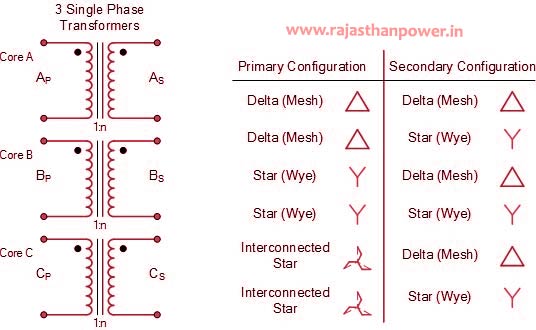
Distribution Transformer Connection
The Distribution Transformer comprises three transformers either isolated or combined with one core.There are four conceivable connections for a Distribution Transformer
- Δ – Δ (Delta – Delta) Distribution Transformer Connection
- Υ – Υ (Star – Star) Distribution Transformer Connection
- Δ – Υ (Delta – Star) Distribution Transformer Connection
- Υ – Δ (Star – Delta )Distribution Transformer Connection
Distribution Transformer Winding Identification
| Connection | Primary Winding | Secondary Winding |
| Delta | D | d |
| Star | Y | y |
| Interconnected | Z | z |
Υ – Υ (Star – Star) Connection
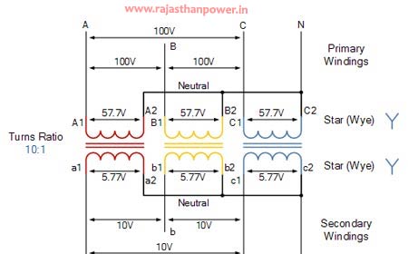
- Star-star connection is generally used for small, high-voltage transformers. Because of star connection, number of required turns/phase is reduced (as phase voltage in star connection is 1/√3 times of line voltage only). Thus, the amount of insulation required is also reduced.
- The ratio of line voltages on the primary side and the secondary side is equal to the transformation ratio of the transformers.
- Line voltages on both sides are in phase with each other.
Delta-Delta (Δ-Δ) Connection :
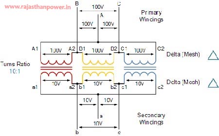
- his connection is generally used for large, low-voltage transformers. Number of required phase/turns is relatively greater than that for star-star connection.
- The ratio of line voltages on the primary and the secondary side is equal to the transformation ratio of the transformers.
- This connection can be used even for unbalanced loading.
Υ – Δ (Star – Delta ) Connection (OR Wye-Delta)
- The primary winding is star star (Y) connected with grounded neutral and the secondary winding is delta connected.
- This connection is mainly used in step down transformer at the substation end of the transmission line.
- The ratio of secondary to primary line voltage is 1/√3 times the transformation ratio.
- There is 30° shift between the primary and secondary line voltages.
Δ – Υ (Delta – Star) Connection(OR Delta-Wye (Δ-Y))
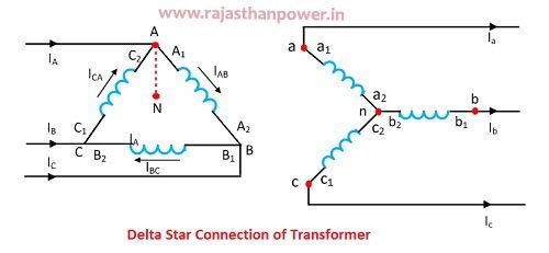
- The primary winding is connected in delta and the secondary winding is connected in star with neutral grounded. Thus it can be used to provide 3-phase 4-wire service.
- This type of connection is mainly used in step-up transformer at the beginning of transmission line.
- The ratio of secodary to primary line voltage is √3 times the transformation ratio.
- There is 30° shift between the primary and secondary line voltages.
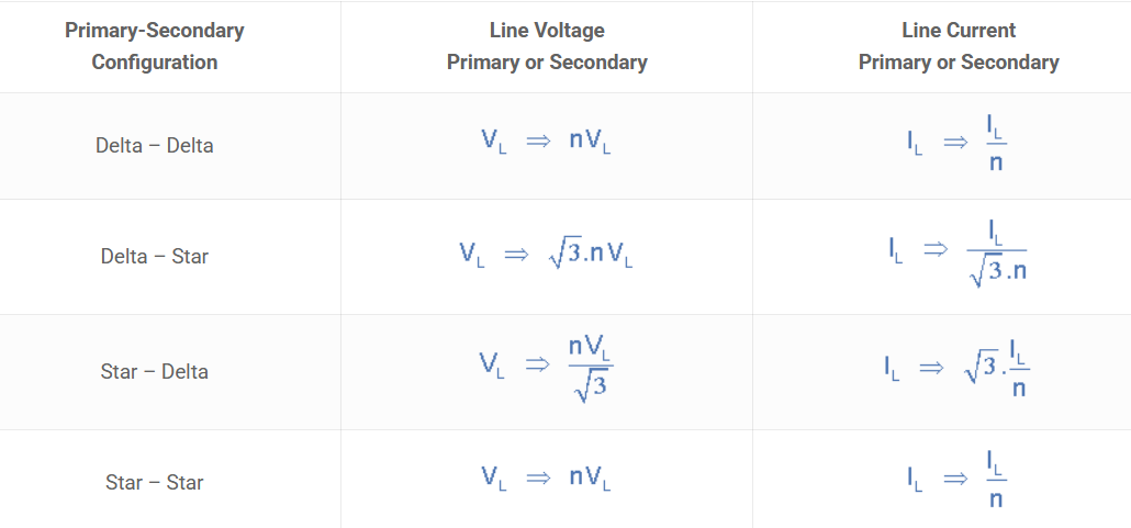
Distribution Transformer Line Voltage And Current
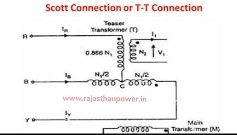
Scott (T-T) Connection
Two transformers are utilized in this type of association. One of the transformers has middle taps on both essential and auxiliary windings (which is called as primary transformer). The other transormer is called as teaser transformer. Scott connection can moreover be utilized for three phase to two phase transformation.
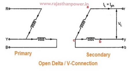
Open Delta (V-V) Connection
Open delta association can be utilized when one of the transformers in Δ-Δ bank is debilitated and the benefit is to be proceeded until the defective transformer is repaired or supplanted. It can too be utilized for little three phase loads where establishment of full three transformer bank is un-necessary.
three phase auto transformer connection diagram
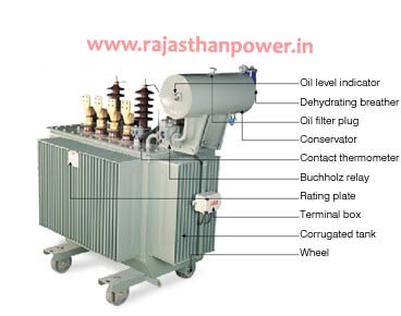
Distribution Transformer Parts
These are the basic components of a Distribution transformer.
- Insulating materials
- Windings
- Laminated core
- Tap changer
- Transformer oil
- Cooling tubes
- Explosion vent
- Breather
- Oil Conservator
- Buchholz Relay
Distribution Transformer Maximum Efficiency
The effectiveness of distribution transformer is characterized as the proportion between output power to input power of the transformer at full load condition, but in case of a distribution transformer, the concept could be a small bit distinctive as the possibility of running a distribution transformer at its full load condition is about nil. The productivity of the transformer is most extreme at 50% of full load.A distribution transformer cannot be run with consistent load all through 24 hours. At day peak time it’s loading is high, though in night lean time its loading may be insignificant.
Distribution Transformer Diagram
distribution transformer protection
All we know that a transformer works as a heart of an electrical framework. As a basic and an costly component of the power frameworks, transformers play an critical part in power conveyance and the judgment of the power framework arrange as a entirety. Transformer disappointments and security dangers can be avoided or minimized by guaranteeing that the conductors and hardware are appropriately measured, ensured and enough grounded. Inaccurate establishment of transformers can result in fires from disgraceful security, as well as electric stun from insufficient grounding.
- Once the transformer is placed, the tank must be permanently grounded with a correctly sized and properly installed permanent ground.
- All equipment used in the handling of the fluid (hoses, pumps, etc.) should be clean and dry. If the insulating liquid for inspection is drawn out, its level should not go below the top of windings.
- Dry air should be continuously pumped into the gas space if humidity exceeds 70%.
- Access should be restricted to the transformer liquid-filled compartment in conditions of excessive humidity or rain.
- Transformer should be given protection against rain such that no water gets inside.
- Surge arresters must be installed and connected to the transformer bushing / terminals with the shortest possible leads to protect the equipment from line switching surges and lightning.
- Upon loading the transformer it should be kept under observation during the first few hours of operation. All temperatures and pressures should be checked in the transformer tank during the first week of operation.
- Sufficient gas pressure must be maintained to allow a positive pressure of 1 psi to 2 psi at all times (even at low amb.temp.) when liquid-filled transformers are stored outside.
- Final inspection of the transformer is essential before it is energized. All electrical connections, bushings, draw lead connections should be checked.
Distribution Transformer fault types/protection methods
| No. | Fault Type | Protection used |
| 1. | Primary winding Phase-Phase fault | Differential; Overcurrent |
| 2. | Primary winding Phase-Earth fault | Differential; Overcurrent |
| 3. | Secondary winding Phase-Phase fault | Differential |
| 4. | Secondary winding Phase-Earth fault | Differential; Restricted Earth Fault (REF) |
| 5. | Interturn Fault | Differential; Buchholz |
| 6. | Core Fault | Differential; Buchholz |
| 7. | Oil tank Fault | Differential; Buchholz; Tank Earth |
| 8. | Overfluxing | Overfluxing |
| 9. | Overheating | Thermal |
power transformer and distribution transformer
Distribution transformer vs power transformer
| Power transformer | Distribution transformer |
| Power transformers are utilized in transmission network of higher voltages for step-up and step down application (200 kV, 400 kV, 66 kV, 110 kV, 33kV) and are generally evaluated over 200MVA. | Distribution transformers are utilized for lower voltage conveyance systems as a implies to conclusion client network. ( 6.6 kV, 11kV, 440V, 3.3 kV, 230V) and are generally appraised less than 200 MVA. |
| Power transformer is utilized for the transmission reason at heavy load, high voltage more prominent than 33 KV & 100% effectiveness. | The distribution transformer is utilized for the conveyance of electrical energy at low voltage as less than 33KV in industrial reason and 440v-220v in domestic reason |
| Power Transformers are utilized in Transmission network so they don’t straightforwardly interface to the customers, so load variances are exceptionally less. | Power Transformers are utilized in Conveyance Network so specifically associated to the consumer so load vacillations are exceptionally high |
| Power transformers are utilized for transmission as a step up gadgets so that the I2r loss can be minimized for a given power flow | Distribution transformers clearly cannot be planned like this. Subsequently the all-day-efficiency comes into picture whereas planning it. |
| The most difference between power and distribution transformer is distribution transformer is outlined for greatest efficiency at 60% to 70% load | Distribution Transformer is utilized at the distribution level where voltages tend to be lower |
distribution transformer advantages and disadvantages
Advantages of distribution transformer:
- less size
- Higher efficiency
- Less cost
- Easier to install
- Require less space
- Less Weight
- Easy transportation and installation
- Deliver more power
- Less time require to assembling
Disadvantages of distribution transformer:
- increased cost and inconvenience of repairs.
- Greater cost of standby Units
types of transformer available
distribution transformer gauges
Temperature controls are required in arrange to turn on and off the cooling equipment. These controls are ordinarily combined with a obvious dial-type gauge that measures ‘winding temperature’.This is truly a misnomer since the gauge does not really contact the winding.Instead, it measures the best oil temperature also a temperature slope delivered by a little radiator encompassing the thermometer bulb.
Winding and/or top oil temperatures should be routinely watched to see whether the transformer is working inside typical temperature limits. There have been numerous cases where an unusual temperature sign has revealed genuine issues with transformers.An oil level gauge is required so that the proper oil level can be kept up. There’s usually a stamp on the gauge that demonstrates the 25°C level, which is the correct oil level at that temperature.
distribution transformer hs code
| HS Code | Description |
|---|---|
| 85043100 | Transformer E3010102 (Sz-Tr-Ab109167) Input 230v, Output 167ma, 9v (Other Than Out Door Type Oil Immersed Distribution |
| 85043100 | Transformer Sz314133-241-1 (10v 500ma) (Other Than Out Door Type Oil Immersed Distribution Transformer ) |
| 85043300 | 75 Kva Single Phase Distribution Transformer ( Re Exportbasis For Testing Purpose) |
| 85043300 | 100 Kva Single Phase Distribution Transformer( Re-Export Basis For Testing Purpose) |
| 85042200 | Re-Import After Testing Of Oil Cooled Distribution Transformer (Copper Wound) With All Fitting & Acc (Exp Sb No.8250948 |
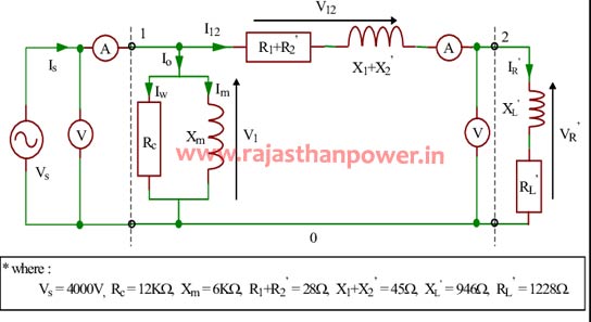
distribution transformer circuit diagram
List Of Distribution Transformer Manufacturers In India
- Rajasthan Powergen Transformer P. Ltd.
Distribution transformer for sale
|
|
CPRI Aprroved electrical distribution transformer, power distribution transformer manufacturers, see pole mounted transformer, 100 kva pole mounted transformer price
ERDA Approved distribution transformers suppliers, aluminium wound distribution transformer, 200 kva distribution transformer manufacturer in India, get distribution transformers catalogue
types of transformer available
- Single Phase Transformer
- Three Phase Transformer
- Distribution Transformer
- Power Transformer
- Inverter Transformer
- Solar Transformer
- Dry Type Transformer
- Amorphous Transformer
- Industrial Transformer
- Electric Furnace Transformer
- Heat treatment transformer
- Environment Friendly Transformer
- Low Losses Transformer
- BIS Approved Transformer
- 3 Star Transformer
- 4 Star Transformer
- 5 Star Transformer
- Energy Efficiency Level 2
- Energy Efficiency Level 3
- CPRI Aprroved Transformer
- ERDA Approved Transformer
- 1 MVA Transformer
- 1.5 MVA Transformer
- 2 MVA Transformer
- 2.5 MVA Transformer
- 3.15 MVA Transformer
- 5 MVA Transformer
- 8 MVA Transformer
- 10 MVA Transformer